 手机版
手机版 化工仪器网手机版
 化工仪器网小程序
 官方微信
官方微信 公众号:chem17
 扫码关注视频号


Application
This procedure is used to determine the resistance to coating adhesion loss of coated surfaces of aluminum,plastic, steel, and other substrates when subjected to a wet blast similar to that produced by vehicle wash equipment.
Apparatus and Materials Required
Film Thickness Gauge
per Ford Laboratory Test Method BI 117-01
Carbide Tip Scribe
CTS (General Scribe #CM 88) - or equivalent
12015 egraph Rd.
Detroit, Michigan U.S.A.
(313) 531-7668
Utility Knife
Stanley, Quick Point 10-300 - or equivalent
(break away tips)
Water Immersion Tank
Per Ford Laboratory Test Method BI 104-01
Note: Thermal shock testing requires:
a. 38 +/- 2 °C water temperature
b. 5 ppm maximum dissolved solids
Heater/Circulator
Fisher Scientific 13-874-70J - or equivalent
Dissolved Solids Meter
Myron L Company - or equivalent
833 East Broadway
San Gabriel, California
Freezer
Capable of minus 29 +/- 2 °C temperature
Steam Generator
a. Input flow of water to be 2.7 +/- .1 L/min (*).
b. Nozzle diameter to be 12.5 +/- .3 mm ID and at least 100 mm long.
c. Discharge dynamic head to be 37.9 +/- 1.9 kPa measured 25 mm from the nozzle using
?? a 4.7 mm ID tube. A substantially non-diverging discharge is required for this test (**)
?? (***) (see Figures 1 and 2).
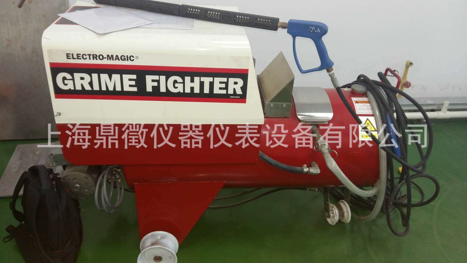
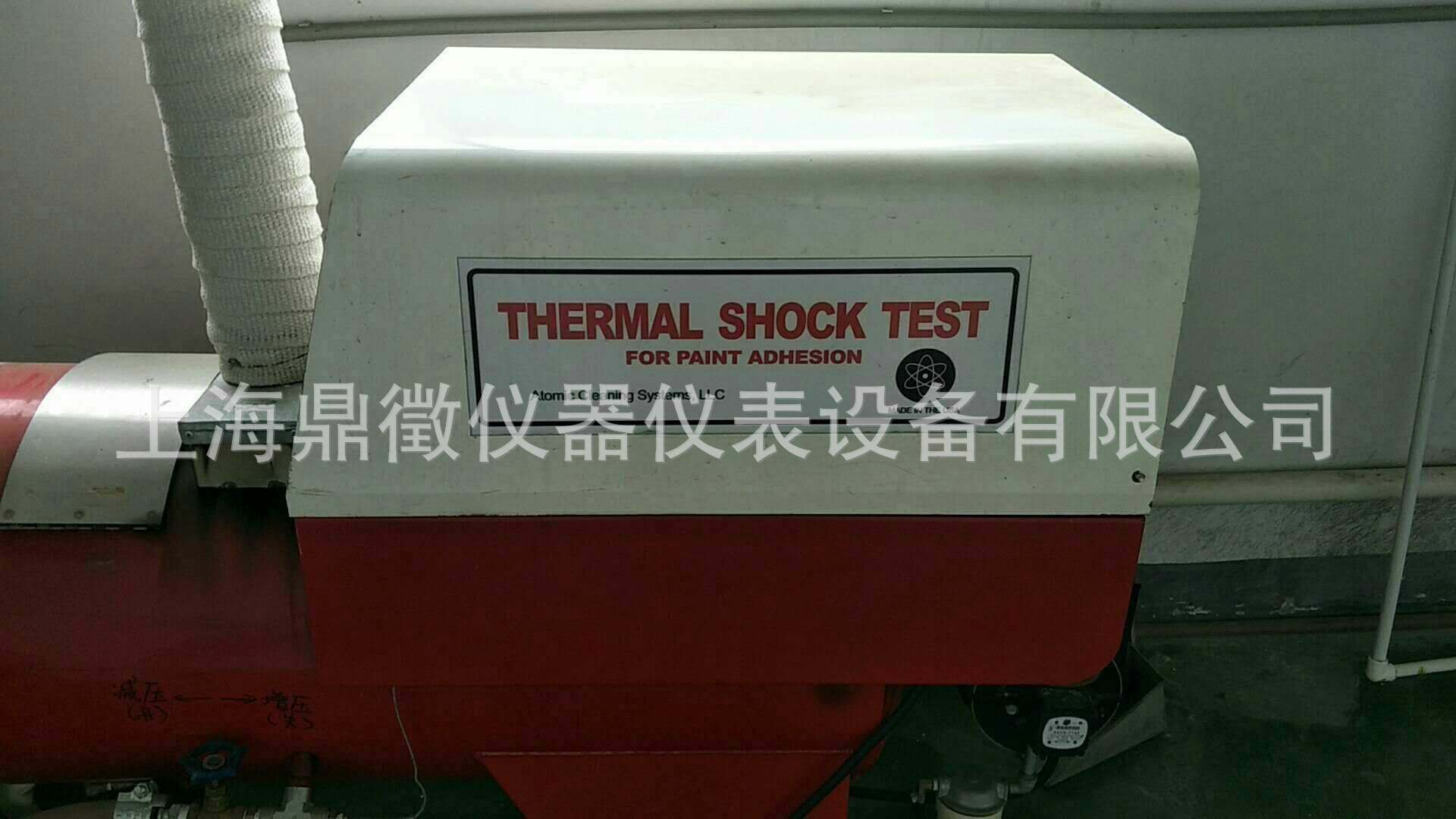
Note: Electro-Magic Model 100 (and the earlier Model 60) Steam Generator available only
from:Atomic Cleaning Systems, 31651 West Eight Mile Road, Livonia, MI 48150, Phone:
?? (248) 615-4400, has been found to be satisfactory. The Model 100 or Model 60 are no
?? longermanufactured directly by Electro-Magic. However, Atomic Cleaning Systems is
?? capable ofmodifying new Electro-Magic models to meet the Model 100 specifications
required for this test.Milwaukee 1/2 inch globe valve No. 1151-1161, 150 SWP 300 WOg
?? is adequate for use in standardization of generator.
Model 100 Steam Generator
(*) The pumping pressure is directly related to the input flow rate. The pressure needed for
therequired flow can be determined by measuring the pump pressure and discharge
flow rate withthe burner off. When the burner is turned on, the required flow rate is
?? obtained by readjusting to the required pump pressure.
(**) This is done by placing the tube midstream 25 mm from the nozzle. The tube size must
?? not bevaried because the densities and velocities are not uniform throughout the cross
?? section of thedischarge stream.
(***) Adjusting the discharge dynamic head may be required. This must be done in such a
way thatthe input flow rate as specified in Para (a) above is maintained. This is done by
adjusting the amount of heat transferred to the water. Increasing the heat will cause the
flow rate (pressure) of (a) to change. It must be readjusted. This operation will result in an
?? increased dynamic pressure; to decrease it, decrease the heat and then adjust the flow
?? (pressure).
Thermometer
?? Capable of measuring 100 +/- 2 °C
Face Mask
Full face cover safety mask is required when performing this test.
Gloves
Gauntlet-type gloves for protection of hands are required.
Conditioning and Test Conditions
All test values indicated herein are based on material conditioned in a controlled atmosphere of 23 +/- 2 ??C and 50 +/- 5 % relative humidity for not less than 24 h prior to testing and tested under the same conditions unless otherwise specified.
Procedure
1. Standardize the Model 60 or Model 100 Steam Generator.
a. Measure and maintain the input flow at 2.7 L/min. Install a 12.5 mm globe valve in the
?? steam line between coil weld assembly and a 5/32 inch hose nipple. With burner off,
?? engage pump and adjust globe valve until 2.7 L/min is obtained.
Record the tank pressure that is obtained with the 2.7 L/min flow rate. (This induced
back pressure simulates the pressure that steam exerts on the system while the burner
is on.)
b. Measure and maintain the mean dynamic head at 37.9 kPa (5.5 psi) using the fixtures as
described in Figures 1 and 2. Open globe valve and turn on the burner. Allow tank
?? pressure tostabilize before reading the mean dynamic head. Adjustments of the
dynamic head are to be made by changing the amount of heat transferred to the water
?? at the burner. (The flow rate, as specified above, must be maintained.)
c. Measure and maintain a 98 +/- 2 °C temperature of the steam blast at the test
?? sitedistance.
2. Measure film thickness per Ford Laboratory Test Method BI 117-01 at proposed test sites
and record.
3. Immerse the parts or panels (previously prepared per Engineering Materials Specification)
?? in the water immersion tank for four hours at 38 +/- 2 °C. Aerate the water by placing 6.5
?? mm ID plastic tube at the bottom of the tank and bubble air at a rate of one bubble per
?? second minimum. Maintain a 5 ppm maximum dissolved solids (as NaCl) in the water.
?? Check and record NaCl level using a dissolved solids meter.
4. Remove the samples after four hours of water immersion and cut an "X" through the
?? coating into the substrate across the panel or part where feasible (see Figure 3).
a. Use a scribe to make the cut if the substrate is metal or hard, rigid plastic.
b. Use a utility knife to make the cut if substrate is an elastomeric material.
5. Place the test samples in a freezer at minus 29 +/- 2 °C for a three hour minimum freeze
cycle.
6. Within 30 seconds from freezer removal, direct the steam blast at the center of the "X" cut,
?? at a distance of 2 to 3 inches and 45° to the sample, in the direction shown in Figure 3.
Note: High pressure wet steam represents a potential safety hazard. Not only is it necessary|
to secure the samples properly, but full face protection and gloves are required.
7. After 30 seconds, record area (mm2) of coating removal by visually measuring with a
?? metric ruler (typical triangular coating removal: Area = 1/2 Base x Height). Also examine
?? the surface and report any blushing, whitening, or loss of gloss.
8. If a failure occurs, note number of seconds after steam black initiated that the failure
occurred.
Chemicals, materials, parts, and equipment referenced in this document must be used and handled properly.
Each party is responsible for determining proper use and handling in its facilities.
ATTACHMENT ONE
RATING SCALE FOR
THERMAL SHOCK TEST PANELS
RATING PEEL BACK
20 = No removal
19 = < 0.5 cm^2
18 = < 1.0 cm^2
17 = < 1.5 cm^2
16 = < 2.0 cm^2
15 = < 2.5 cm^2
14 = < 3.0 cm^2
13 = < 3.5 cm^2
12 = < 4.0 cm^2
11 = < 4.5 cm^2
10 = < 5.0 cm^2
9 = < 5.5 cm^2
8 = < 6.0 cm^2
7 = < 6.5 cm^2
6 = < 7.0 cm^2
5 = < 7.5 cm^2
4 = < 8.0 cm^2
3 = < 8.5 cm^2
2 = < 9.0 cm^2
1 = < 9.5 cm^2
0 = > 9.5 cm^2
SEE SPECIFICATION FOR ACCEPTANCE CRITERIA RATING

Figure 1

Figure 2
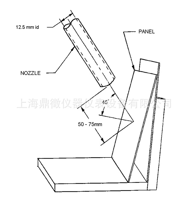
Figure 3
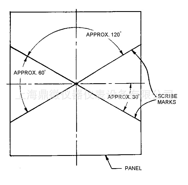
Figure 4

免责声明
- 凡本网注明“来源:化工仪器网”的所有作品,均为浙江兴旺宝明通网络有限公司-化工仪器网合法拥有版权或有权使用的作品,未经本网授权不得转载、摘编或利用其它方式使用上述作品。已经本网授权使用作品的,应在授权范围内使用,并注明“来源:化工仪器网”。违反上述声明者,本网将追究其相关法律责任。
- 本网转载并注明自其他来源(非化工仪器网)的作品,目的在于传递更多信息,并不代表本网赞同其观点和对其真实性负责,不承担此类作品侵权行为的直接责任及连带责任。其他媒体、网站或个人从本网转载时,必须保留本网注明的作品第一来源,并自负版权等法律责任。
- 如涉及作品内容、版权等问题,请在作品发表之日起一周内与本网联系,否则视为放弃相关权利。


 采购中心
采购中心