 手机版
手机版 化工仪器网手机版
 化工仪器网小程序
 官方微信
官方微信 公众号:chem17
 扫码关注视频号


In-line Illumination Considerations
In-line illumination is a unique style of lighting that incorporates the illumination into the optical train of the machine vision lens, usually by means of a fiber optic light guide or LED light source and a beam splitting optic. Although in-line illumination is not as bulky as diffuse axial illumination, and may be easier to integrate into a system that has tight space constraints, there are important optical differences a system designer must consider. In-line illumination is much more directional when compared to diffuse axial lighting, which, due to the chief rays being nearly parallel to the optical axis in object space, is one of the reasons that in-line illumination is widely incorporated with ecentric lenses (Figure 1). In comparison, diffuse axial lighting will project the illumination at a multitude of different angles, displaying ‑different properties on the object and image planes.
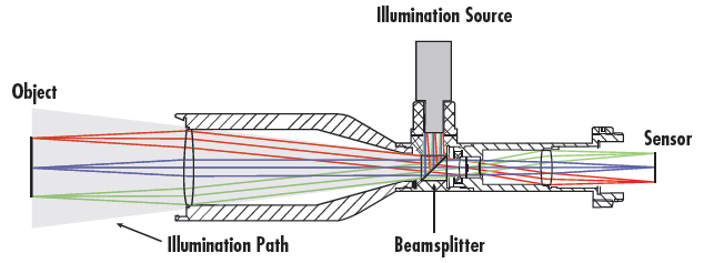
Figure 1: Diagram of In-Line Illumination within a ecentric Lens
Vastly different results will also come from comparing in-line illumination to bright field illumination. Figure 2 shows a chrome on glass, positive USAF 1951 contrast target illuminated both with bright field illumination and with in-line illumination.
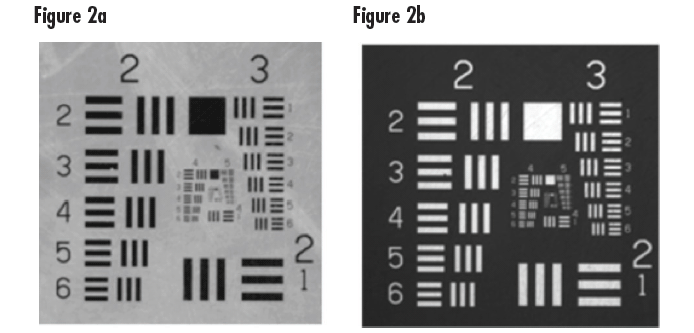
Figure 2: Chrome on Glass USAF 1951 Resolution Target with Bright Field Illumination (Figure 2a), and In-Line Illumination (Figure 2b)
The most immediate difference between the two types of illumination is the complete contrast reversal between the two images. Additionally, the defects in the target are more readily apparent in the bright field image, which, depending upon the application, can be either a positive or a negative effect. Interestingly, the highly reflective nature of the target yields about 10% better contrast for the in-line image when compared to the bright field image – the reason for this is explained below.
When to Use In-Line Illumination
When considering using in-line illumination, it is important to understand exactly where it is applicable and where it is not. In-line illumination is ideal for the inspection of specular or semi-specular objects, such as semiconductor wafers or CCDs, due to the nature of the rays on the illumination path. Using two different ecentric lenses, one with in-line illumination and one without, images of the same CCD demonstrate the ‑differences between bright field illumination (using a ring light) and inline illumination. The images are shown in Figure 3.
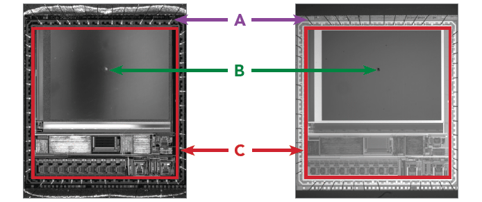
Figure 3: Comparison of Brightfield Illumination (left) with In-line Illumination (right)
In-line illumination would be a better choice to inspect the wires along the edge of the CCD due to the higher, more even contrast between the wires and the rest of the CCD. As shown in Figure 4, the reason that the wires in Figure 3 appear bright using bright field illumination and dark using in-line illumination is due to the ray paths of the lighting. With bright field illumination, the rays are scattered into the lens, and with inline illumination, the rays are scattered away from the lens.
With bright field illumination, the rays originating from the ring light are reflected by the object into the lens. The reflections will vary based on the angle of the individual sources in the ring light as well as the angle of the wires themselves with respect to the CCD surface and the solder material at the tips, which is why the reflections have non-uniform pixel values along the length of the wire. Using in-line illumination, all of the rays are reflected by the object and scattered away from the lens such that none of the light that hits the wires is reflected back into the lens and onto the sensor. The more even contrast of the background, along with the stronger contrast of the wires, makes in-line illumination a better choice for the inspection of the wires than bright field illumination.
Comparison of Brightfield and In-line Illumination | |
Brightfield Illumination | In-line Illumination |
Low Contrast | High Contast Wires |
Bright Chip on Faceplate | Dark Chip on Faceplate |
High Contrast Image | Even Illumination with Consistent Contrast between Features (red square) |
If the CCD cover glass were to be inspected for digs or chips, in-line illumination would also be the more advantageous choice since the overall image has a much more even contrast. The dark chips shown using in-line illumination (a result of the light being scattered as shown in Figure 4) would appear at a much higher contrast to the busy CCD background than the chips shown in the high contrast image formed using a brightfield system, as demonstrated in Figure 3.
When Not to Use In-Line Illumination
Due to its multiple advantages, it is often believed that in-line illumination is always the superior choice for space-constrained systems. Unfortunay, it is not the best solution for objects that are optically diffuse or for objects requiring a large field of view. When used with diffuse objects, in-line illumination produces a hotspot on the image caused by the Lambertian (a nearly constant bidirectional reflectance distribution function) tendencies of the object, which is detrimental to any inspection system. Figure 4 shows an image of a diffuse object of wooden material both with (right image) and without (left image) in-line illumination.
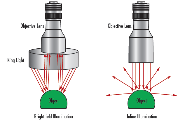
Figure 4: Comparison of Ray Paths Using Brightfield Illumination (left) and In-line Illumination (right)
When the primarily Lambertian object is in-line illuminated, the image has a well-defined hotspot in the center of the field of view. This hotspot effectively washes out the desired contrast, yielding a contrast of about 70% for the brightfield image, and about 8% for the in-line illuminated image, with both contrast values taken at the center of the image.
There are, of course, other situations where in-line illumination is not the ideal option. When a large field of view is required, the étendue of the illumination system becomes a problem, in that spreading out the flux of the light over a large field inherently leads to a much less dense bundle of photons, and therefore has a negative impact on the throughput of the system as a whole. Imperfect light sources also significantly and negatively impact the performance of inline illumination systems with large fields of view, as the small imperfections are bolstered over the large projection in the object plane.
In-line illumination would be a better choice to inspect the wires along the edge of the CCD due to the higher, more even contrast between the wires and the rest of the CCD. As shown in Figure 2, the reason that the wires in Figure 1 appear bright using brightfield illumination and dark using in-line illumination is due to the ray paths of the lighting. With brightfield illumination, the rays are scattered into the lens, and with in-line illumination, the rays are scattered away from the lens.
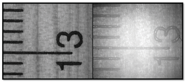
Figure 5: Comparison of Wooden Object with Brightfield Illumination (left) and In-Line Illumination (right)


免责声明
- 凡本网注明“来源:化工仪器网”的所有作品,均为浙江兴旺宝明通网络有限公司-化工仪器网合法拥有版权或有权使用的作品,未经本网授权不得转载、摘编或利用其它方式使用上述作品。已经本网授权使用作品的,应在授权范围内使用,并注明“来源:化工仪器网”。违反上述声明者,本网将追究其相关法律责任。
- 本网转载并注明自其他来源(非化工仪器网)的作品,目的在于传递更多信息,并不代表本网赞同其观点和对其真实性负责,不承担此类作品侵权行为的直接责任及连带责任。其他媒体、网站或个人从本网转载时,必须保留本网注明的作品第一来源,并自负版权等法律责任。
- 如涉及作品内容、版权等问题,请在作品发表之日起一周内与本网联系,否则视为放弃相关权利。


 采购中心
采购中心